Trash Talk
Trash Talk is a prototype for an inexpensive, mesh-networked, democratic public address system. Each node contains a speaker, a microphone, a radio, and an easy to use single-button interface. To send a message, simply walk up to any node, press the button, and talk.
In this prototypal stage, each trash talk unit costs approximately $20 in parts. The goal for the project is to create units that are so inexpensive they can be regarded as disposable, enabling users to install them with impunity in public spaces everywhere. To keep units hidden, they are embedded in inocuous looking trash.


Download
If you're interested in building your own or scouring this project for parts, you can download all of my schematics, layouts, and code here: trash_talker-2008-05.tar.gz. Note that this is a is a prototype and not a kit; constructing it is complicated, and you'd get best results by emailing me for assistance.
Technical Details
Here is a basic structural overview of the Trash Talk unit:
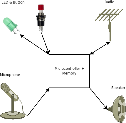
The microcontroller used is a AVR ATmega88 (datasheet). This microcontroller has (just barely) enough pins to interface all the required hardware, has an on-board ADC to read the microphone with, and has a pseudo-DAC in the form of a fast PWM timer.
The microcontroller is connected to an Atmel DataFlash IC (specifically, the AT45DB081D), a 1-megabyte flash memory chip with an SPI interface. Because this memory requires a maximum voltage of 3.6V, the microcontroller and everything else is regulated to 3.3V. The speaker amplifier receives unregulated power from the battery to maximize amplitude.
Circuit Design


Microphone Amplifier
The microphone itself is a small, cheap electret mic. I used the "Knowles Acoustics" MB6022APC-O, available from digikey.
The microphone amplifier for this circuit is a modification of Neil Gershenfeld's design (Neil's cad.py format design). It is your basic single-supply non-inverting opamp circuit, but with some bandpass filtering in the feedback loop.

This application would really benefit from some compression on the amplifier circuit -- to proportionally amplify low volume sounds more than high volume, allowing for more predictable volume levels regardless of microphone proximity.
Speaker Amplifier
Coming up with a design for the speaker amplifier was much less straightforward. The signal coming from the microcontroller is a Pulse-Width Modulated signal -- that is, it is a square wave with a varying duty cycle. The variation in the duty cycle is the analog signal; but the part of the signal with the most energy is the "carrier" or "modulation", which is around 30kHz. This is above human hearing range, so we could ignore it. But if we don't ignore it and send it into a standard linear amplifier, the amplifier will saturate with this inaudible signal, and be less able to amplify the lower frequency parts of the signal that we care about.
One potentially awesome tangent that researching these amplifiers took me to is the realm of class-D amplifiers. A class-D amplifier is a relatively new type of amp, which operates as a "switching amplifier", which are known for high efficiency and light weight. They operate precisely by generating a PWM signal from a regular audio signal, and using it to drive what is essentially an H-bridge, with the speaker as the load. Since the microcontroller's output is already a PWM, it seems to make sense to use this to drive an H-bridge-like thing as an amplifier. After multiple designs and partial success (I eventually managed to build amps that did have adequate volume, but only at high input voltages), I returned to linear amplifiers, as they seemed to get better results at lower current. I would like to return to class-D amps for microcontrollers at some point.
Ultimately, I settled on using a Phillips TDA7052A, a 1-watt Bridge-tied-load linear amplifier. I used a two-stage RC filter on the input to remove as much of the PWM modulation signal as I could, but there is still a fair amount of amplitude at 30kHz in the resulting signal. An active filter might achieve better results without degrading the target frequencies of 10kHz and under.

Radio
The radio I chose is the Integration Associates IA4421, an ISM-band (433/860/915Mhz) transceiver that is very cheap and performs quite well (though it is a little on the small side, and its documentation could be better). The main challenge with the transceiver is to design a good antenna. For this prototype I used the "Back IFA" design from Integration Associates' older Antenna Selection Guide, which I made with copper vinyl on a wood substrate. For future work I am researching better antenna designs.
The radio as I set it up uses 7 pins on the microcontroller -- but with slight modification to the code this could be reduced to the 4-pin SPI interface alone (the extra pins reduce polling requirements and slightly increase data clocking efficiency).


User Interface
Simple user interface: button and LED. Couldn't be simpler.
The board is also set up with an RS-232 serial interface so debugging data can be sent out and audio prompts can be loaded in. To do serial interfacing, I used Neil Gershenfeld's hack -- let 0v be the "low" (instead of the RS-232 spec's -12V), and VCC by the "high" (instead of the RS-232 spec's +12V). That way, you don't need a line driver for serial transmission, and it still works with every computer I've ever tried. For computer to serial communication, all you need is a resistor and a zener diode to clamp the incoming voltage down to VCC/~0v.
Code
All the software is coded in Atmel AVR Assembler. For ease of development, I split the code into several useful modules:
- RS232.asm and RS232_bauds.asm -- code for software-driven line-driverless serial. Also, see rx.py, a convenient python program for printing serial data in a variety of formats.
- AT45DB.asm -- opcodes and routines to run the AT45DB DataFlash IC's (requires a 2-buffer model like the AT45DB081D).
- MEGA88_code.asm -- some useful macros and routines for commonly used ATMega88 stuff.
- IA4421_config.asm and IA4421_code.asm -- configuration and routines to drive the IA4421 radio transceiver.
- delays_8MHz.asm -- software delay routines for AVRs running at 8MHz (and avr_delay.py to generate delay routines for other durations and clockspeeds)
- trunk.asm and DPA_UDP.asm -- The code that runs the Trash Talker application, handling recording, playback, and the "mesh networking" routines.
All files in an archive: trash_talker-2008-05.tar.gz
Mesh Networking
Code-wise, the mesh networking component of this project is the part that is of most interest, so I describe it in detail here.
Because I am using the cheap, high-bandwidth IA4421 radios (much cheaper than equivalent Xbee or Nordic radio modules by an order of magnitude), and because these radios don't come with a native networking stack like Zigbee, I had to come up with my own way to do mesh networking. I wanted a system that required no central infrastructure at all, was self organizing, could have any unit removed without affecting the other units, and could have units added easily.
Fortunately, there are some simplifications in my system that might not be present in a normal networking scenario: there is only one important piece of data on the network at any time (the latest audio recording), and every message is intended for every unit. This alleviates the need for any fancy routing and addressing -- each unit is just a broadcaster and a repeater. What would be a very difficult problem of determining routing becomes the less difficult, but still challenging problem if merely preventing loops in the broadcast chain -- making sure that two units don't bounce the same packet back and forth against each other forever, clogging up the channel. Beyond this, each unit can just rebroadcast the messages it receives in a logical order, and messages will extend to the leaves of the network.
Here are the important components of the network protocol for this application:
- Physical Layer: provided by the radio. I used the radio's native bit slicing and signal strength detection.
- Medium Access: For medium access control (that is, who is allowed to talk when), I implemented CSMA -- essentially, "listen before you talk." Every time a unit is about to send a packet, it listens first and processes what it hears.
- Packet protocol: I used UDP packets without IP headers. The source and destination ports of the UDP packets are used to determine the function of the packet. The UDP checksums are used to verify packet validity. There are no packet acknowledgements or retransmit requests -- since the messages are sent repeatedly, a recipient with only partial reception should eventually get the whole message.
Application: The trash talker transmits exactly three different types of packets:
- . "Announce" packets -- announcing a new recording.
- . "Data" packets -- audio data.
- . "Execute" packets -- instruction to playback recording now.
Each packet contains a unique ID for the sender (used to prevent retransmission loops), a unique ID for the recording (used to identify when recordings change), a packet type ID, and a repeat ID that indicates how many times this packet has been sent by the initial sender (used to allow retransmissions of packets without re-execution). This is all that is needed for "Announce" and "Execute" packets (they need send no additional data), but "Data" packets also have a payload of audio data, and a sequence ID that indicates where in the recording that audio data fits.
Here is the packet structure:
<td>+</td><td>Bits 0-15</td><td>16-31</td>
 <td class='heading'>0</td>
         <td>
           "Source Port": <br />
           byte 0: sender ID<br />
           byte 1: recording ID
         </td>
         <td>
           "Destination port":<br />
           byte 0: packet type<br />
           byte 1: repeat count
         </td>
  <td class='heading'>32</td>
          <td>Length (always 128 bytes)</td>
          <td>Checksum</td>
  <td class='heading'>64</td>
          <td colspan='2'>Data (Audio packets only): sequence ID and audio (120 bytes)</td>
Packet Processing Algorithm
Each unit spends most of its time listening for packets, and when it receives one, it executes the "process packet" algorithm. There are a number of conditions the algorithm must check for to ensure that loops don't occur, but that beneficial retransmission does:
- The packet must be valid
- The "source ID" must not be the same as that of the receiving unit
- The packet must be current -- either related to the current recording in the system, or announcing a new recording.
- The packet must not have already been processed.
Beyond that, the algorithm must properly handle the three different packet types described above. Here is a flowchart describing the algorithm:

New Recordings
The button on the user interface triggers an interrupt which is serviced immediately. If the user confirms the new recording, the unit will attempt to stop all other units in range immediately so it can send its new data. To do this, it broadcasts an "Announce" packet several times, waiting for a while in between each broadcast, which signals each unit to stop transmitting old data.

Every time the transmitter sends any data, it first listens to ensure the line isn't busy, and to process any incoming packets which might signal an even newer recording.
In this prototype, the originator of a message (that is, the unit into which the message was recorded) is the only unit which initiates sending of messages. Consequently, if that unit were removed from a network, the message would stop playing, though new messages could be added to other nodes in the network. It should be possible to alleviate this problem by building in a time-out, whereby a unit will begin to initiate messages on its own if it fails to receive any packets after a period of time.
Future
While this prototype does successfully create a mesh-networked PA system, it does not do so in so inexpensive a manner that the units can be considered disposable. This seriously constrains the intended use cases of communication in publicly oppressive spaces where removal if the units is inevitable. However, other use cases might still benefit, where the desired product is simply an extensible, low-infrastructure ad-hoc PA system.
It seems unlikely that in the near future the cost of this prototype will substantially decrease. Current cost breakdown for the major components is as follows:
- Microcontroller: ~$3
- Radio and parts: ~$5
- Speaker: ~$4
- Amplifiers: ~$2
- Battery: ~$5
- Other components: ~$6 total
- Total: ~$25
This estimate is based on relatively low volumes of parts, and the cost would go down in higher volume purchases, but not by the order of magnitude needed to turn this into a disposable product, especially given that multiple units are needed for the system to be effective.
Audio, as it turns out, is very difficult for microcontrollers to deal with. Where mere communication is the concern, the cost of peripherals to deal with audio data is higher than image data, since the image data needs only a single low-resolution frame to transmit a message, but audio requires a sampling rate of several kilohertz at a few bits per sample to be intelligible. This imposes higher requirements on memory and bandwidth. It would be interesting to explore the use of systems like this for textual or image-based data.
Another way to keep costs down is to leverage existing infrastructure, such as cell phones or FM radios, where such infrastructure is present.